 |
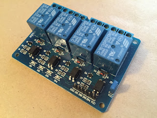
| 4 Way Relay Board |
The inputs are protected from the "heavy lifting" of energising the relay coils by opto-isolators. Grounding an input pin allows current to flow from the +5VDC supply through a current limiting resistor, a surface mount red LED, and then the LED within the opto-isolator. The forward current is about 2mA in this situation so it's fine to directly connect these inputs to digital I/Os on an Arduino. The relay coils are wired to the +5VDC supply and the opto-isolator phototransistor collectors, and each is provided with a usual flyback diode. (Note that the +5VDC supply might get in the way of using one of these boards with a Raspberry Pi; these use 3.3V digital I/Os and could be damaged by higher voltages.)
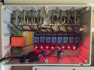
So far I've built a box with an 8 way relay board and connected it to 8 external lamps. A small AC-DC module provides +5VDC locally; I will locate the control system elsewhere, with the link to the relay box containing just relay control lines and ground in a multi-core cable.
 |
| 8 Way Relay Board - Driving Lights |
Have you seen http://www.theregister.co.uk/2016/04/14/intel_takes_aim_at_arduino_with_us15_breadboard/ ?
ReplyDeleteI've just caught up with Intel's Quark. The Pentium instruction set at 32MHz, burning 25mW, is astounding! And the board price speaks for itself. Happy days for hobbyists.
ReplyDelete