Showing posts with label embedded. Show all posts

Wednesday, 9 March 2016

Arduino 16x2 LCD/Keypad Shield

Many embedded projects benefit from a user interface, and shields with a 16x2 LCD and a 5 button keypad are popular with Arduino users. Most are almost exactly like this one. As with many Arduino peripherals, they are very inexpensive - less than 6 GBP at the time of writing for the one I chose with first class postage within the UK, less still if you can wait for one from China.

Arduino LCD/keypad Shield
Boards such as this are often referred to as "1602A" type, with various manufacturers adding various prefixes and suffixes. They all seem to be based on the Hitachi HD44780 LCD controller (or a compatible clone). And most seem to use a 4-bit parallel interface to this controller (which can also support 8-bit operation). The keypad buttons are wired with a resistor ladder between the power rails so that a unique voltage corresponding to each button is delivered into one of the MCU's ADC inputs.

There are various examples and drivers available for 1602A display/keypad boards running on the Arduino, but I wanted to understand it from first principles, so I coded my own simple driver in C after studying the controller datasheet and the board schematic. This allows you to clear and write strings to the display, and read debounced key presses. I wrote a quick demo program in C using Atmel Studio 7 for this which you can download here.

Note that the documentation is not reliable when it comes to the character set burned into the controller's ROM. The upper 128 character codes in my module did not match the data sheet, so - for example - I had to create a user defined character to get a "degree" symbol for the temperature reading shown in the above picture.

Here's a video showing the demo program running:


Tuesday, 8 March 2016

Arduino Real Time Clock

I needed an accurate real time clock for an Arduino based home automation project; many are I2C controlled and based on Maxim's DS3231 which is achieves an accuracy of about 1 minute per year (2ppm) through temperature compensation - a potentially useful side effect of this is that the part provides a temperature reading. Most boards also include an I2C EEPROM. I found a seller on eBay offering 3 units for under 5 GBP, including next day postage:

Real Time Clock and EEPROM board

The board provides a header with 6 pins:
  • GND - ground
  • VCC - power (3.3V or 5V)
  • SCL - I2C clock
  • SDA - I2C data
  • SQW - programmable interrupt/square wave output
  • 32K - free running 32kHz clock output
There's a holder for a CR2032 coin cell on the reverse, to provide battery backup. Note that these are typically not included with the boards (there are international restrictions on shipping lithium batteries).

I hooked it up to my Arduino Mega 2560 with male-female flying leads: I wired GND and VCC to GND and 5V on the power header, SCL and SDA to their counterparts on the communication header, and the SQW output to the INT3 input.

I then wrote a quick program in to test the board (I prefer to code in C using Atmel's Studio for AVR microcontroller development, for more on this see here.) This used the nice, stable and simple I2C master driver written by Peter Fleury. Note that I ignored the board's EEPROM.

The program prints the current time, day, date and temperature once a second:

       
RTC test
time: 12:14.44   day: TUE   date: 08/03/2016   temperature: +24.00
time: 12:14.45   day: TUE   date: 08/03/2016   temperature: +24.00
time: 12:14.46   day: TUE   date: 08/03/2016   temperature: +24.00


The program uses the Arduino's USB serial port for console I/O, based on Mika Tuupola's recipe here. I use TeraTerm on a desktop Windows PC for this, connected to the Arduino's COM port at 115200 baud.

You can download a ZIP of the Atmel Studio 7 project from here.

Monday, 22 February 2016

Raspbian Jessie Lite

A new lightweight version of Raspbian Jessie has been released. It looks promising for “headless” applications (no monitor, keyboard or mouse). I fired it up on my Raspberry Pi Model B.

You can get Raspbian Jessie Lite from here. At the time of writing, the version was dated 2016-02-09 and the kernel version was 4.1. The ZIP download weighed in at 365MB. This contained a similarly sized compressed IMG file. Next, I had to write this image to SD card.

Note that choosing a reliable SD card is something of a science, with guidance available from various sources. For example, see here. I chose an 8GByte Lexar micro SD card that came bundled with an SD card adapter. I bought it from Amazon because of their no-fuss returns policy:

Lexas 8GB microSDHC card with SD adapter
The procedure for writing to image to SD cards can be found  here. I followed the Windows recipe, first extracting the IMG from the ZIP, and then running Win32DiskImager to write the IMG to my SD card:
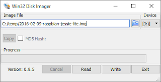
Win32DiskImager application

It took a few minutes to get these steps done. I then inserted the freshly written SD card in the Pi, connected it to the HDMI input of my monitor, and plugged in an ethernet cable. Boot messages appeared on the monitor within a couple of seconds of power on. The login prompt appeared after maybe 20-30 seconds:
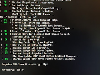
First Boot
First Boot

I then switched my monitor back to displaying the output from my desktop PC, aiming to use an ssh client to interact with the now fully headless Pi. There are plenty to choose from; my favourite is PuTTY.

To make life easier on my LAN, I use static IP addresses for various devices, such as my NAS, and including my Raspberry Pi. To do this, I reserve an address in my DHCP server’s configuration, linking the device's MAC address to a fixed IP address. For the Pi I chose 192.168.1.9, as shown on the PuTTY configuration dialog:


PuTTY Launch Window
PuTTY Launch Window

After double-clicking the raspberrypi entry (to Open it), I blew past the ensuing security warning by clicking Yes. A terminal window then appeared, and I was then able to log in with the usual default credentials (username = pi, password = raspberry):

PuTTY Terminal Window

Many images assume a 2GB SD card and size things accordingly, meaning wasted space on larger cards. I checked, and this was indeed the case:

       
pi@raspberrypi:~ $ df -h
Filesystem      Size  Used Avail Use% Mounted on
/dev/root       1.3G  912M  281M  77% /
devtmpfs        214M     0  214M   0% /dev
tmpfs           218M     0  218M   0% /dev/shm
tmpfs           218M  4.4M  214M   3% /run
tmpfs           5.0M  4.0K  5.0M   1% /run/lock
tmpfs           218M     0  218M   0% /sys/fs/cgroup
/dev/mmcblk0p1   60M   20M   41M  34% /boot


raspi-config can be used to fix this:

       
pi@raspberrypi:~ $ sudo raspi-config


You simply highlight option 1 and hit Enter...
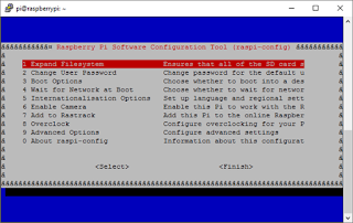
raspi-config in action

...and a few seconds later you can reboot and the job is done. I did this, and checked the outcome:

       
pi@raspberrypi:~ $ df -h
Filesystem      Size  Used Avail Use% Mounted on
/dev/root       7.3G  913M  6.1G  13% /
devtmpfs        214M     0  214M   0% /dev
tmpfs           218M     0  218M   0% /dev/shm
tmpfs           218M  4.4M  214M   3% /run
tmpfs           5.0M  4.0K  5.0M   1% /run/lock
tmpfs           218M     0  218M   0% /sys/fs/cgroup
/dev/mmcblk0p1   60M   20M   41M  34% /boot


Notice that /dev/root now has 6.1G available.

I will be trying to use the resulting setup for a few embedded projects.

AVR Studio 7 and the Arduino Mega 2560

I've heard of the Arduino family of microcontroller boards but have not worked with one until today. I decided to take a closer look because I do know the Atmel AVR, in particular the 8-bit mega family, and an Arduino is a reasonably cheap way to get one to experiment with. I chose an Arduino Mega 2560 board.

My AVR experience is based on various editions of Atmel's Studio IDE - so I wanted to find out how to use it with the Arduino hardware, ignoring the Arduino software as much as possible.

Here are the steps I followed to run a simple C program. My starting point was a fresh install of Atmel Studio (version 7.0.783) and the Arduino software (version 1.6.7) on a desktop PC running Windows 10 - and (of course) an Arduino Mega 2560 connected to the PC via USB, with it's green power LED on.

(Note that you can click on an image to see a full size / full resolution version.)

  • on the Start Page, select New Project...
    AVR Studio Start Page
    Atmel Studio 7 - Start Page
  • in the New Project dialog, select GCC C Executable Project, specify a Name and a Location then click OK
    Atmel Studio 7 - New Project dialog
    Atmel Studio 7 - New Project dialog
  • in the Device Selection dialog, select ATmega2560 (the type of AVR microcontroller used on the Arduino board) then click OK
    Atmel Studio 7 - Device Selection dialog
    Atmel Studio 7 - Device Selection dialog
  • a minimal, template project is created, ready for you to enter code...
    Atmel Studio 7 - Virgin Project
    Atmel Studio 7 - Virgin Project
  • choose test Properties (assuming your project is called test) from the Project menu, then select Toolchain, and under AVR/GNU C Compiler select Symbols
    Atmel Studio 7 - Project Properties tab
    Atmel Studio 7 - Project Properties tab
  • in the Defined Symbols (-D) box, click the Add Item button and enter F_CPU=16000000UL (this specifies the processor clock frequency in Hertz; for the Arduino Mega 2560 this is 16MHz - the "UL" suffix means Unsigned Long)
    Atmel Studio 7 - adding a defined symbol
    Atmel Studio 7 - adding a defined symbol
  • select the main.c tab and enter enough C code to see life signs - mine pulses the "L" LED once then twice, over and over
    Atmel Studio 7 - entering a simple C test program
    Atmel Studio 7 - entering a simple C test program
       
#include <avr/io.h>
#include <util/delay.h>

int main(void)
{
 DDRB |= (1 << PORTB7); // PORTB7 direction = out
 
 while (1)
 {
  
  // 1 pulse
  PORTB |= (1 << PORTB7); // PORTB7 hi = LED L on
  _delay_ms(500); // 0.5 sec
  PORTB &= ~(1 << PORTB7); // PORTB7 hi = LED L off
  
  // delay
  _delay_ms(2000); // 2 sec

  // 2 pulses
  PORTB |= (1 << PORTB7);
  _delay_ms(500);
  PORTB &= ~(1 << PORTB7);
  _delay_ms(500);
  PORTB |= (1 << PORTB7);
  _delay_ms(500);
  PORTB &= ~(1 << PORTB7);

  // delay
  _delay_ms(2000);
 }
}

  • now the interesting part - adding support for the Arduino's programming mechanism, which requires the use of the avrdude utility that is included in the Arduino software installation

    • first, identify the COM port that the Arduino is connected to by running the Device Manger - in my case it was COM3...
      Device Manager (Windows 10) showing Arduino COM port
      Device Manager (Windows 10) showing Arduino COM port
    • choose External Tools... from the Tools menu
      Atmel Studio 7 - External Tools dialog (before)
      Atmel Studio 7 - External Tools dialog (before)
    • in the External Tools dialog...
      • change the Title to Program
      • enter the following in the Command box:
               
        c:\Program Files (x86)\Arduino\hardware\tools\avr\bin\avrdude.exe
        
        
      • enter the following in the Arguments box, changing -P COM3 to match the COM port that the Arduino is connected to on your machine:
               
        -v -C"C:\Program Files (x86)\Arduino\hardware\tools\avr\etc\avrdude.conf" -p atmega2560 -c wiring -P COM3 -b 115200 -D -U flash:w:$(TargetDir)$(TargetName).hex:i
        
        
      • check the Use Output window box
      • click OK
        Atmel Studio 7 - External Tools dialog (after)
        Atmel Studio 7 - External Tools dialog (after)
    • there is now a Program option on the Tools menu which will flash the compiled code into the Arduino board - let's add a corresponding shortcut to the UI:
      • select Add or Remove Buttons to the right of No Tool, then Customize...
        Atmel Studio 7 - adding a custom button
        Atmel Studio 7 - adding a custom button
      • the Customize dialog appears:
        Atmel Studio 7 - Customize dialog
        Atmel Studio 7 - Customize dialog
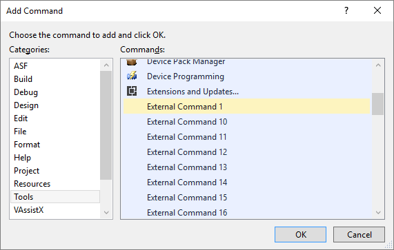
      • click Add Command...
      • under Categories select Tools
      • under Commands scroll down and select External Command 1
        Atmel Studio 7 - Add Command dialog
        Atmel Studio 7 - Add Command dialog
    • click OK then Close the Customize dialog
    • there is now a Program button left of the device (ATmega2560) button
  • to build the code, choose Build Solution from the Build menu (or hit F7):
    Atmel Studio 7 - after build
    Atmel Studio 7 - after build
  • now program the board by clicking the Program button - this will produce some rapid progress messages from the avrdude programming utility in the Output pane:
    Atmel Studio 7 - after programming
    Atmel Studio 7 - after programming
  • voila - you should see the "L" LED blinking once then twice, repeatedly